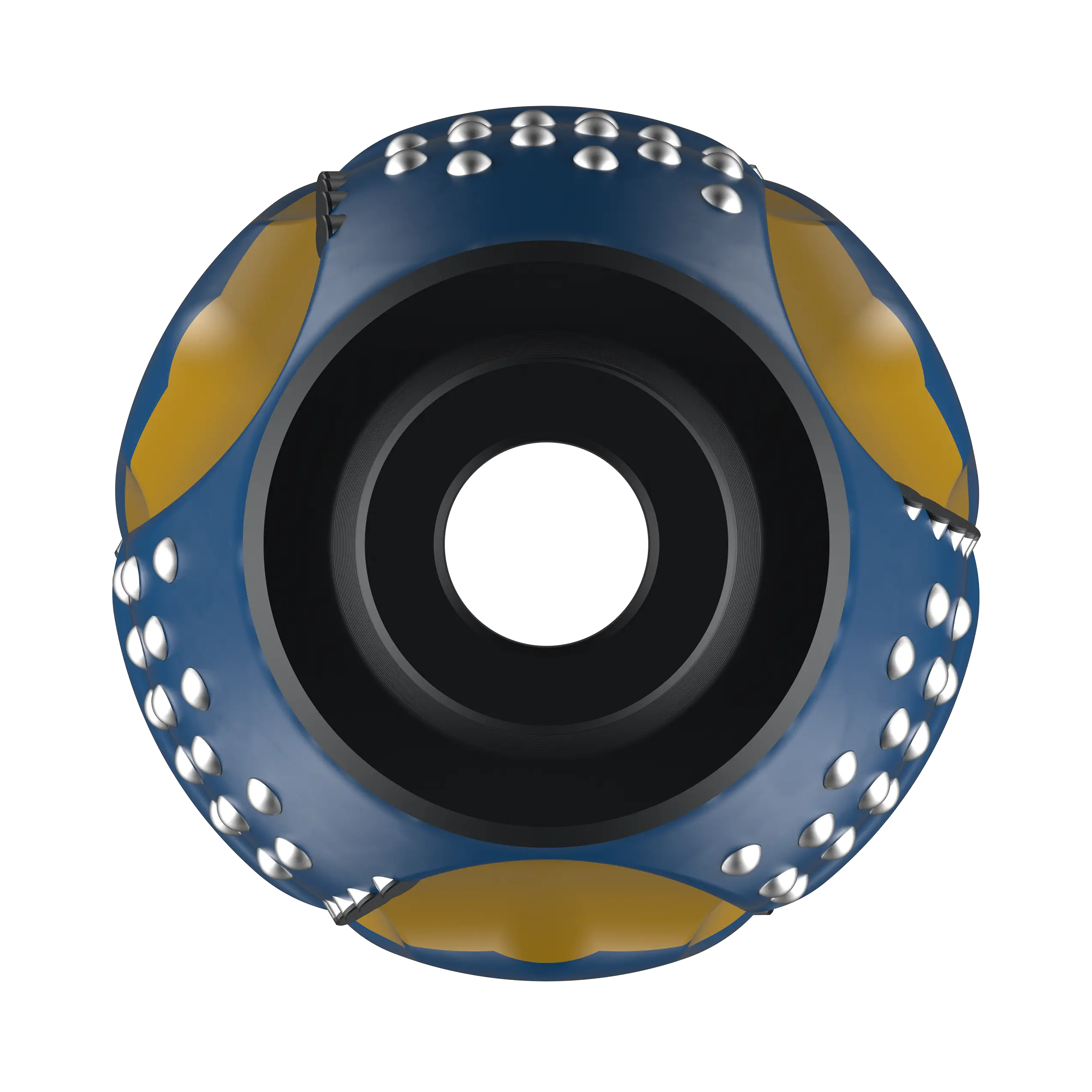
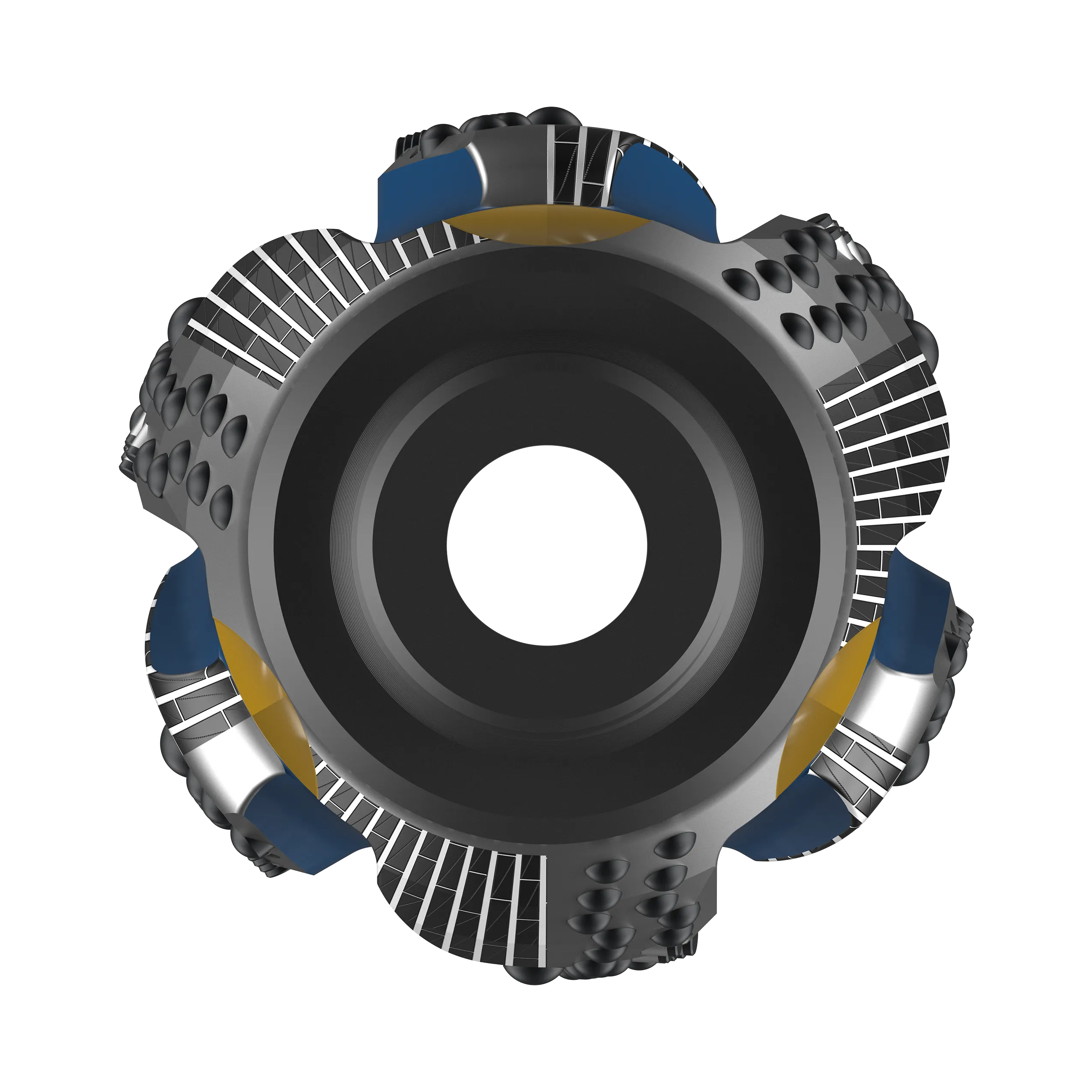
The ClearPath eccentric reamer is designed to improve drilling efficiency by removing sections of parallel misalignment, keyseats, micro doglegs and assisting in scouring and displacing cutting beds that can lead to swabbing and pack-off issues.
The ClearPath eccentric reamer achieves this through the optimized placement of a low-torque helical hybrid cutting structure, combined with a flow accelerator and drill cuttings agitator.
To enhance overall drilling efficiency, we have developed a hybrid multifunctional wellbore conditioning system. This system ensures a smoother wellbore through a unique two-stage reamer, drilling fluid accelerator, and cutting bed agitator — all integrated into a single-piece design.
The ClearPath eccentric reamer is an innovative multifunctional tool combining reaming, drilling, wellbore conditioning, improved stabilization, and hole cleaning capabilities.
The ClearPath eccentric reamer is manufactured from a single piece of steel. The steel used has mechanical properties which are compatible with other drill string components connecting to the eccentric reamer.
The first and second reamer blade sets are angularly displaced about the longitudinal tool axis by 180° on the drill string. Circumferentially opposing dual drift blades which are hard banded and are positioned to dynamically stabilize the cutting structure whilst reaming. This offset reamer blade arrangement marginally enlarges the wellbore diameter, ensuring the bit can pass through without the need for back reaming.
Each eccentric reaming blade surface has deep helical grooves running up the blade, with PDC cutters and dome-shaped inserts located in the center tooth bed. The cutting structure cuts into the doglegs, and cuttings are pulled up the flute by the rotation of the tool and into the longitudinal blade flow by-pass area.
The first set of reamer blades contains the active cutting structure, and hence does most of the borehole enlarging, while the second set of blades further condition. The stabilizer blades positioned circumferentially at 180° on the drift side dynamically stabilize the tool during rotational reaming.
The middle section, between the lower and upper reamer blades, contains design features which increase the velocity and impel cutting beds. These features work in tandem as the tool translates in a counter rotation, agitating the cutting beds on the lower side of the wellbore up into the circulating drilling fluid where they are transported up the annulus. The additional bearing pressure and increase in annular velocity combined with stabilizer blade pad geometry leads to a smoother filter cake whilst minimizing the risk of packing off during drilling operations.
As the reamer translates in a counter rotation downhole, as drilling fluid and suspended cuttings and cavings flow past the agitator blades located between the first and second reamer blade set. In doing so, the geometry of the agitator blade elements increases the velocity of the drilling fluid, thus creating turbulence in the mid-tool annulus, and a cleaning effect on the wellbore wall due to bearing pressure created against the wall of the wellbore.
Bit Diameter |
Drill Diameter |
Drift Diameter |
---|---|---|
5 7/8″ | +0.0625″ | -0.125″ |
6″ | +0.0625″ | -0.125″ |
6 1/8″ | +0.0625″ | -0.125″ |
6 1/4″ | +0.0625″ | -0.125″ |
6 3/4″ | +0.0625″ | -0.125″ |
7 7/8″ | +0.1250 | -0.125″ |
8 3/8″ | +0.1250 | -0.125″ |
8 1/2″ | +0.1250 | -0.125″ |
9 1/2″ | +0.1250 | -0.125″ |
9 7/8″ | +0.1250 | -0.125″ |
11 5/8″ | +0.1875 | -0.125″ |
12″ | +0.1875 | -0.125″ |
12 1/4″ | +0.1875 | -0.125″ |
16″ | +0.2500 | -0.125″ |
17 1/2″ | +0.2500 | -0.125″ |
Bit Diameter |
Collar OD (in) |
Tool ID (in) |
---|---|---|
5 7/8″ | 5.000″ | 2.000″ |
6″ | 5.000″ | 2.688″ |
6 1/8″ | 5.250″ | 2.813″ |
6 1/4″ | 5.250″ | 2.688″ |
6 3/4″ | 5.250″ | 2.688″ |
7 7/8″ | 6.125″ | 2.835″ |
8 3/8″ | 6.750″ | 2.835″ |
8 1/2″ | 6.750″ | 3.000″ |
9 1/2″ | 6.750″ | 2.250″ |
9 7/8″ | 7.000″ | 2.250″ |
11 5/8″ | 8.250″ | 3.000″ |
12″ | 8.250″ | 3.000″ |
12 1/4″ | 8.250″ | 3.000″ |
16″ | 9.500″ | 3.000″ |
17 1/2″ | 9.500″ | 3.000″ |
Series | Weight (kgs) |
Weight (lbs) |
---|---|---|
6″ | 175 | 385 |
8 1/2″ | 350 | 770 |
12 1/4″ | 710 | 1565 |
17 1/2″ | 1290 | 2840 |
Ream when you need to, not because you can. The Dome hybrid reamer, a stabilizer while drilling, a reamer when you need one. This innovative design has a similar profile to the FixedBlade stabilizer but offers an overall longer blade length to support a unique three-stage taper with different cutter types. The 3-stage taper is created to ensure a gradual cutting action starting at 14 degrees at the bottom, 5 degrees in the middle, and 2 degrees as a transition zone to the hardfacing.
The pin-side has numerous TCIs spread out over the 3-stages with flat PDC cutters positioned near the hardfacing for extra protection. The box-side is set up similarly but also integrates different stud PDC cutters for extra backreaming capabilities.
The Dome hybrid reamer is the ideal tool to position as the top stabilizer for extra protection for the BHA, ensure backreaming capabilities, without intervening with any weight on bit or torque issues.
Passive reaming capability up-and-down
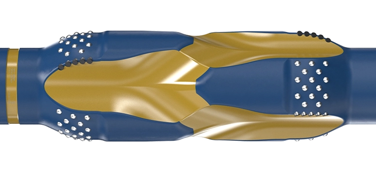
The 3-stage taper is created to ensure a gradual cutting action starting at 14 degrees at the bottom, 5 degrees in the middle, and 2 degrees as a transition zone to the hardfacing.
The FixedBlade reamer is engineered to achieve optimal borehole gauge while effectively minimizing wellbore imperfections, including borehole tortuosity. This is achieved through the controlled elongation of micro doglegs and borehole spiral patterns during the drilling process.
To maximize its efficiency, the FixedBlade reamer should be positioned high-up in the drill string and operated under tension.
Bi-directional reaming capabilities
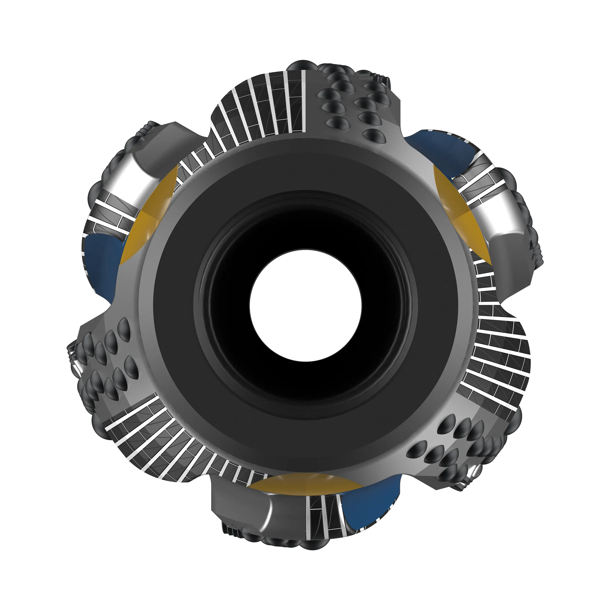
The FixedBlade reamer boasts an advanced design featuring optimized hydrodynamics, enabling enhanced transportation of cuttings surrounding the stabilizers.
The cutter configuration allows for forward and back-reaming capabilities.
Hole-Size | Gauge-Range | Length (m) | Weight (kg) | ID | Fishing Neck Diameter |
Surface Area (in2) |
Connection |
---|---|---|---|---|---|---|---|
6″ series | 5 3/4″ – 6 1/4″ | 2.00 | 180 | 2″ | 4 3/4″ | 100 | NC38 |
8″ series | 8″ – 8 1/2″ | 2.20 | 360 | 2 1/4″ | 6 3/4″ | 220 | 4 1/2″ IF |
12″ series | 12″ – 12 1/4″ | 2.40 | 660 | 2 13/16″ | 8 1/4″ | 240 | 6 5/8″ Reg |
17″ series | 14 3/4″ – 17 1/4″ | 2.60 | 1200 | 3″ | 9 1/2″ | 340 | 7 5/8″ Reg |